Shaft diameters
Measure each real shaft and decide whether the printed bore should slide, locate or be finished after printing.
 EazyMake 3DUseful parts. Made easy.
Editable spur gear template
This starter pairs an 18-tooth gear with a 36-tooth gear at module 1.5. Change the tooth counts, bores, face width and backlash, then export the two gears and a smaller backlash trial from the same parameter set.
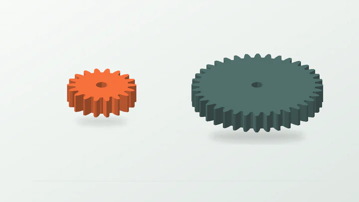
A transparent way to explore a printable external gear pair while keeping ratio, centre distance, bore fit and backlash visible.
The starter dimensions are there to make the controls understandable. Replace them with evidence from the real part, space and print setup.
Measure each real shaft and decide whether the printed bore should slide, locate or be finished after printing.
The starter's nominal pitch-centre distance is 40.5 mm; confirm the mounting geometry can place both axes correctly.
Check space around both outside diameters, not only the pitch circles, throughout the intended motion.
Confirm the 8 mm starting width, shaft engagement and neighbouring hardware suit the prototype layout.
These values produce the preview shown above. They remain editable after the template opens in the EazyMake studio.
The generator keeps the important decisions visible and carries one parameter set through geometry, inspection, calibration and export.
Choose which shaft drives, the required ratio and the direction change produced by the external gear pair.
Record both shaft diameters, usable centre distance, axial space and the surrounding envelope.
Edit module, tooth counts, pressure-angle settings, face width, bores and backlash without mixing incompatible gear parameters.
Compare the supplied variants on the intended printer setup before producing the complete gears.
Review each generated part and export only after the topology and printable-mesh checks complete successfully.
Answers specific to this starter and the measurements it exposes.
The larger gear has 36 teeth and the smaller has 18. One revolution of the 36-tooth gear corresponds to two revolutions of the 18-tooth gear, with the direction reversed by the external mesh.
For this standard external pair, each pitch diameter is module multiplied by tooth count. Half of 27 mm plus 54 mm gives a nominal pitch-centre distance of 40.5 mm.
Yes. The starter begins with two 5 mm bores, but each gear bore is editable. Measure both shafts and test the intended printed fit.
Not on the evidence provided by generation or slicing alone. A powered or safety-relevant application needs separate material, load, wear, guarding and failure testing.
Use the guide when you need the reasoning, or open another template to see the same measurement-first workflow in a different part family.
Open the real generator, replace the example dimensions and keep the calibration result tied to your printer and material.