Matched involute geometry
Both gears share the selected metric module, pressure angle, root-clearance convention and circumferential backlash.
 EazyMake 3DUseful parts. Made easy.
Editable spur gear generator
Set the module, tooth counts, face width and independent bores for two external involute gears. EazyMake derives their ratio, pitch diameters and nominal centre distance, then creates marked backlash trials from the same shared geometry.
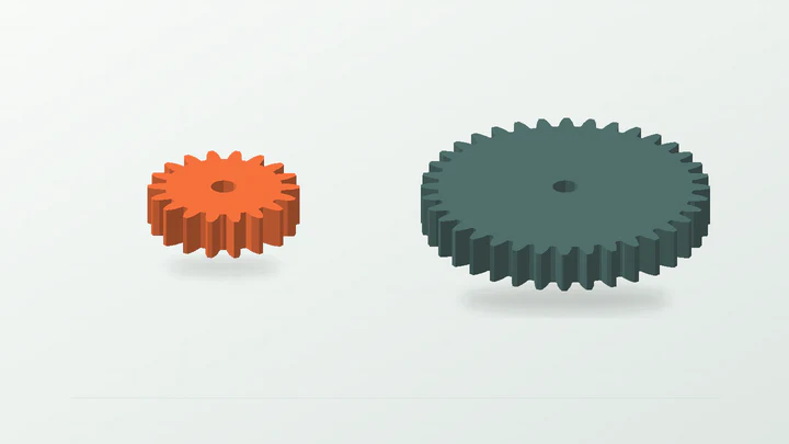
A transparent prototype workflow for matched external gears: shared geometry stays visible, backlash is named, and digital checks remain separate from load or wear evidence.
Start with a bounded workflow, then edit the dimensions and supported features without hiding the fit assumptions.
Both gears share the selected metric module, pressure angle, root-clearance convention and circumferential backlash.
Change Gear A and Gear B tooth counts to explore ratio and envelope while retaining compatible shared tooth geometry.
Size each circular bore for the real shaft, then treat bore fit as a separate calibration question from tooth backlash.
Export tighter, selected and looser equal-size trial pairs so tooth engagement can be compared before the full gears.
The generator can keep dimensions consistent, but the real installation and mating parts remain the source of truth.
Define the input and output shafts, direction change and tooth-count relationship needed by the prototype.
Measure or design the axis spacing; the nominal centre distance is half the sum of the two pitch diameters.
Measure both shafts independently and decide whether each printed bore should slide, locate or be finished after printing.
Check outside diameters, face width, hubs or supports and clearance to neighbouring parts through the complete motion.
Each step keeps the editable parameters, calibration artifact and final printable parts connected.
Choose the driver, driven gear and ratio, remembering that two external gears reverse direction.
Set one module and supported pressure angle for the pair, then select tooth counts that avoid the generator's undercut limit.
Compare the derived pitch diameters, outside diameters and centre distance with the real shaft and housing layout.
Print the marked meshing trials, and run an additional bore experiment when shaft fit is also important.
Inspect and export both gears, then test alignment, support and motion in the complete hand-driven prototype before any broader claim.
Use a template to understand a complete parameter set, then replace its dimensions with your own evidence.
Practical answers about what the current generator does—and what still needs a physical test.
The displayed Gear B-to-A ratio is Gear B's tooth count divided by Gear A's tooth count. Which shaft speeds up or slows down depends on which gear is the driver.
Yes. A meshing pair must share module and pressure angle. The generator keeps those values common while allowing separate tooth counts and bores.
It is the total circumferential clearance at the pitch circle across the meshing pair. The marked trial pairs compare a tighter, selected and looser value.
No. Generation, mesh inspection, export and a smooth manual trial do not establish safe powered use. Material, loads, wear, alignment, supports and guarding need a separate engineering test plan.
Use the guides to choose and record a calibration experiment before treating a trial value as evidence.
Open the generator, choose a bounded starting workflow and keep the relevant physical trial attached to the final project.