Required jaw opening
Measure the workpiece stack and allow deliberate travel for the jaw cartridge, pressure cup and screw engagement.
 EazyMake 3DUseful parts. Made easy.
Editable C-clamp template
This starter builds a 55 mm-opening C-frame with a 45 mm throat, 14 mm printed power screw, hand driver, swivel pressure cup and four side-loading jaw cartridges. Calibrate the matching thread before printing the complete multi-part set.
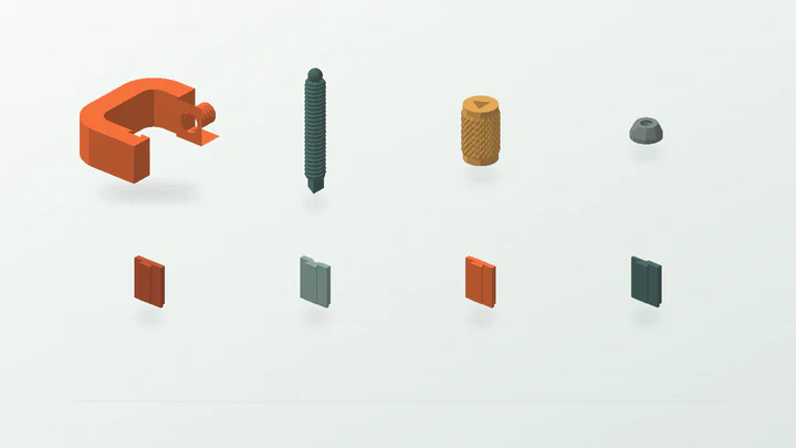
A dimensional workholding prototype for light trials—not a load-rated clamp or evidence for lifting, structural restraint, vehicle work, pressure, electrical or overhead use.
The starter dimensions are there to make the controls understandable. Replace them with evidence from the real part, space and print setup.
Measure the workpiece stack and allow deliberate travel for the jaw cartridge, pressure cup and screw engagement.
Measure from the workpiece edge to the intended pressure line, then allow for the inside spine and chosen jaw face.
Choose flat, V-groove, serrated or stepped jaw contact only after checking the real surface and acceptable marking risk.
Identify load direction, leverage, vibration, heat and consequences of release for a separate physical risk assessment.
These values produce the preview shown above. They remain editable after the template opens in the EazyMake studio.
The generator keeps the important decisions visible and carries one parameter set through geometry, inspection, calibration and export.
Measure the required opening, throat and contact surfaces, then decide whether a printed light-duty prototype is appropriate at all.
Keep screw length, frame thickness, opening and thread engagement compatible instead of changing one dimension in isolation.
Select a jaw cartridge for the trial while retaining access to all four separately printable faces in the project bundle.
Test the short screw against the three marked female rings and record the lowest clearance that turns without binding.
Print the frame on its broad side, inspect layer separation before every use and keep the trial within a separately defined safe test plan.
Answers specific to this starter and the measurements it exposes.
The generator creates the C-frame, power screw, hand driver, swivel pressure cup and four separately printable jaw cartridges: flat, V-groove, serrated and stepped.
A short 14 mm, 3 mm-pitch screw is paired with marked female rings at 0.20, 0.30 and 0.40 mm radial clearance. It tests printed thread fit only.
The template does not establish safe clamping force, duration, creep or failure behaviour. Any real use needs a separate assessment and controlled physical validation for the material, print and workpiece.
Match the contact geometry to the workpiece and acceptable marking risk: flat for broad faces, V-groove for round stock, serrated for an intentionally textured contact or stepped for edge support. None is a holding-force rating.
Use the guide when you need the reasoning, or open another template to see the same measurement-first workflow in a different part family.
Open the real generator, replace the example dimensions and keep the calibration result tied to your printer and material.