Finished panel hole
Measure the actual hole diameter at several angles and inspect burrs, paint, edge damage and out-of-round conditions.
 EazyMake 3DUseful parts. Made easy.
Editable split-grommet template
This removable grommet wraps around a 10 mm cable without unplugging it, then locates in a measured 25 mm panel hole and 2.5 mm-thick panel. Panel fit and cable clearance remain separate dimensions, with a dedicated panel-fit calibration pack.
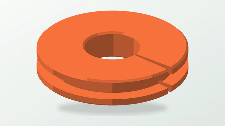
A flexible dimensional prototype for managing an existing cable—not certified electrical insulation, fire protection, strain relief or a load-rated retainer.
The starter dimensions are there to make the controls understandable. Replace them with evidence from the real part, space and print setup.
Measure the actual hole diameter at several angles and inspect burrs, paint, edge damage and out-of-round conditions.
Measure the material where the groove will sit, including coatings or layered construction that changes the local thickness.
Measure the real jacket across its widest practical section and allow for connectors, bends and permitted compression.
Identify temperature, movement, abrasion, electrical, fire and ingress requirements that this printed prototype does not certify.
These values produce the preview shown above. They remain editable after the template opens in the EazyMake studio.
The generator keeps the important decisions visible and carries one parameter set through geometry, inspection, calibration and export.
Record the finished hole, local panel thickness and cable outside diameter before choosing either radial clearance.
Panel radial clearance changes the barrel outside diameter; cable radial clearance changes the internal bore. Do not reuse one number automatically.
Adjust the split gap, lip overhang, lip thickness and edge treatment around the real installation constraints.
Compare the tighter, selected and looser barrel trials, then confirm cable-bore behaviour separately with the actual cable.
Print flat on one lip, install without damaging the cable and assess movement or abrasion without treating the part as certified protection.
Answers specific to this starter and the measurements it exposes.
The 25 mm panel hole minus 0.20 mm radial clearance on both sides gives a 24.60 mm starting barrel outside diameter.
The 10 mm measured cable plus 0.50 mm radial clearance on each side gives an 11.00 mm starting bore. Confirm it against the real jacket and intended movement.
That is the purpose of the full-length split, provided the real cable and connector geometry allow safe installation. The split does not itself prove retention or strain relief.
No electrical or fire certification is provided. Material, voltage, temperature, abrasion, installation and applicable requirements need assessment outside this generator.
Use the guide when you need the reasoning, or open another template to see the same measurement-first workflow in a different part family.
Open the real generator, replace the example dimensions and keep the calibration result tied to your printer and material.